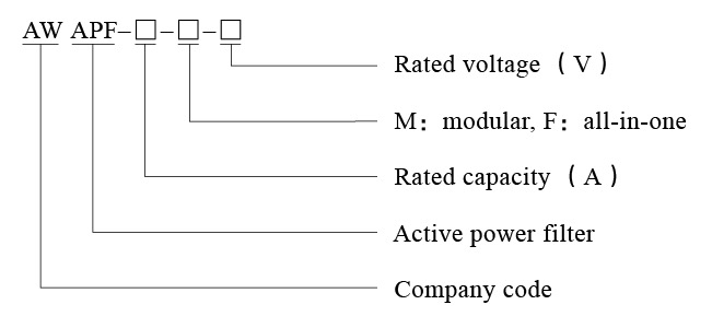
Active filter

AWAPF active power filtering device eliminates harmonics of grids by the most advanced dynamic real-time tracking and compensation method that is available currently. Harmonics are separated after detecting current waveform generated by non-linear load. Then an inverter generates a current that has the same amplitude with but the opposite phase to the load harmonic, so that total harmonic current of the power source is zero, and real-time compensation of harmonic current is realized. Operation of the filter is not influenced by system impedance, system resonance is avoided, self-adaption is realized, variation in harmonic may be tracked automatically, and high controllability and rapid response is ensured.
Active filter

Mode coding


Technical specification

  • Rated voltage:400±15% (may be tailor made based on customers’ demands)
  • Rated frequency:50 Hz or 60Hz
  • Filter range:2~50 times
  • Filter capacity:THDi<3%
  • Transient response time:100µs
  • Input end breaker:breaking capacity shall not be lower than 50kA
  • Overload capacity:120%
  • Efficiency:≥98%
  • Safe operation time (MTBF):≥300,000h
  • Time-delay starting control circuit:Y
  • Protection grade:IP20 (may be tailor made based on customers’ demands)
  • Communication protocol:RS485 MODBUS
  • Connection pattern:parallel connection open loop or closed loop
  • Structure:modular
  • Neutral line filter capacity:3X of phase line
  • Complete response time:<10ms
  • Switching frequency:20kHz
  • Capacity expansion:multiple modules can be installed in parallel


Service conditions

  • Temperature:-25℃~+40℃
  • Humidity:≤95%
  • Maximum elevation and environmental requirements ≤1500m, in the range of 1500m to 4000m
  • No corrosive gas or conductive dusts shall exist in the environment and no strenuous vibration is allowed


Operation principles

AWAPF active power filter detects load current by external current transformer CT, and extracts harmonic component of load current by internal DSP calculation, then sends signal to internal IGBT by PWM, to control inverter to generate a current with the same magnitude but opposite direction to load harmonic and to inject the current into the grid to compensate for harmonic current and filter the current. 


■ Engineering estimation method for harmonic capacity
Multiple factors are involved in calculation of harmonic current. For conventional project, calculation of the harmonic current may utilize power quality analyzer. For new projects, electrical designers may not acquire enough data of electrical device harmonics. Based on the situations, we have concluded the following empirical formula based 
◎ Centralized treatment


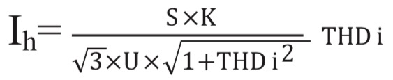
Introduction to parameters of the formula:
S:rated capacity of transformer;
U:rated voltage of secondary side of transformer;
Ih:harmonic current;
THDi:total harmonic distortion of current;
The formula is applicable to centralized treatment of secondary side of transformers. K is load rate of transformers, generally 0.6-0.85 for design of transformers.
◎ Local treatment


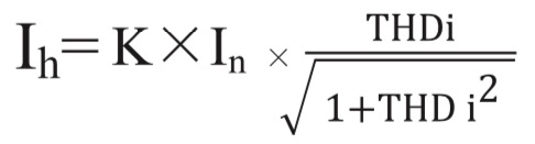
Where, In is rated current of equipment, and K is load rate of loading equipment; if the equipment is running with full load, K=1.

Contact Us